For a friend who is new to PLC or has never used PLC before, how can he quickly get started and understand his basic applications?
First of all, we need to understand what is PLC?
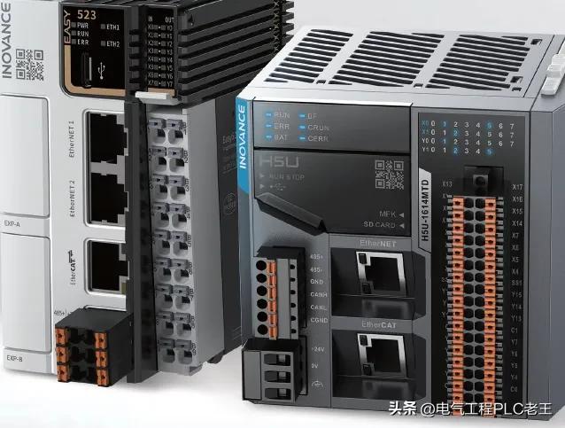
PLC is a programmable controller, which refers to a new type of industrial control device based on computer technology.
PLC composition
The basic composition of PLC mainly includes several parts such as central processing unit, memory, input and output unit, power supply and programmer.
The equivalent circuit of the PLC control system can be divided into three parts, namely the input part, the output part and the internal control part. The input part is to collect the input signal, and the output part is the execution part of the system. These two parts are the same as the traditional relay control circuit. The internal control circuit is logic control realized by programming method, and the function of traditional relay circuit is replaced by software programming.
Generally, PLC user programs are compiled in a graphic language such as ladder diagram. The ladder diagram looks a lot like a traditional relay control circuit diagram, which has the advantage of being intuitive and easy to understand, and can be easily mastered by electricians who are familiar with traditional relay control. It is especially suitable for switching logic quantity control.So we also call the ladder diagram the circuit diagram of the PLC or the program of the PLC.
Next, let's take a look at the hardware introduction of PLC
Take Inovance H5U as an example to introduce
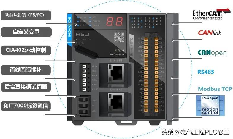
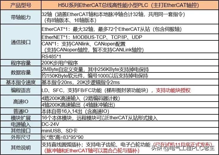
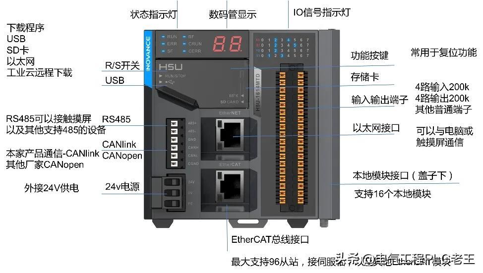
What do we need to understand by looking at the hardware manual?
1. Belt shaft capacity
H5U can carry 32 axes, the control mode is ethercat
2. Local I/O
16 inputs, 14 outputs
It is enough to understand these, and the next step is the simplicity and practicality of the PLC software.
Autoshop software introduction
First, you need to go to the official website to download an autoshop software.
Open the software, let's configure the module first

Choose the IO module according to your own strength needs, and after configuration, the corresponding address will be available.

Here is the specific address corresponding to each module, we can use it directly.
For example, if there is a door lock signal that wants to be connected to the PLC, we can just connect it to the main body input.
Through allocation, you can see that the main body IO is X0-X17.
We can randomly choose a point among the 16 to connect to, for example, connect to X2, then we can find the actual corresponding X2 point wiring of the PLC.
After the wiring is completed, let's see how to write the software
This is the end of the writing, as long as the door lock signal is triggered, the PLC can monitor it.
If you want the touch screen to also see this signal, just read this signal directly on the touch screen.
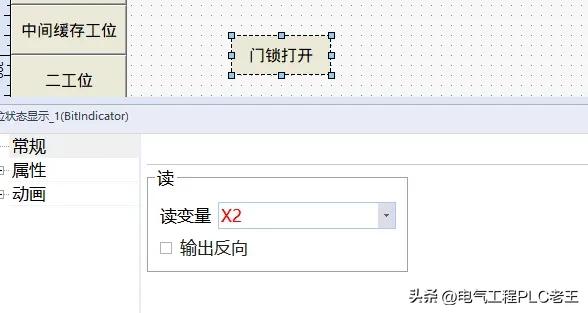
Just make a button like this on the touch screen.
As for other programming, you can directly write according to the language. You can also read my previous articles, which introduce the function blocks of cylinder and axis control.
The most important thing is to master the basic knowledge, and the rest will be smooth.